
 ____       _          ____
|  _ \ ___ | |__   ___/ ___| _   _ _ __ ___   ___
| |_) / _ \| '_ \ / _ \___ \| | | | '_ ` _ \ / _ \
|  _ < (_) | |_) | (_) |__) | |_| | | | | | | (_) |
|_| \_\___/|_.__/ \___/____/ \__,_|_| |_| |_|\___/

  ____            _    _                 _
 / ___|___   ___ | | _| |__   ___   ___ | | __
| |   / _ \ / _ \| |/ / '_ \ / _ \ / _ \| |/ /
| |__| (_) | (_) |   <| |_) | (_) | (_) |   <
 \____\___/ \___/|_|\_\_.__/ \___/ \___/|_|\_\
We’re beginning RoboSumo with a short puzzle called the LED Flash Challenge. No formal assessment weight is attached to this challenge, but we’ll keep an eye on who does well. In this challenge, doing well means:
In today’s lab you’ll work with your classmates to complete two tasks:
The first task is very prescriptive, which basically means that we tell you exactly what to do. The second task requires you to think for yourselves.
You need a team number to complete today's challenge. Your lab supervisor will divide you into teams of three. Your lab instructor will give each team a unique number from the range shown below (room numbers are provisional, pending timetable adjustments):
Please note that today's teams are just for the LED challenge. Later on, you will select your own teams of three for the main part of the RoboSumo project.
When you complete the LED Flash Challenge, please retain the following items so that you can document your work on your RoboSumo blog in the coming weeks:
This task is relatively straightforward and shouldn’t take you too long to get working.
The "breadboard" is the rectangular white plastic board we use to build the circuit. Each short row of five holes is a single electrical connection. Two wires inserted into the same row become connected electrically. Each row is marked with a number and each column is marked with a letter, so that each hole in the main section of the board can be uniquely identified using a letter and number. The instructions below use these letters and numbers to identify the exact position of each component.
Please watch the following video, which provides a very clear explanation of how the breadboard works. In case you don't have earphones with you, subtitles are available in the video.
The breadboard comes with an adhesive strip on the back of it, which is covered by a protective sheet. Do not remove the protective sheet! Once the breadboard sticks to something it cannot be moved without compromising the internal structure of the breadboard.
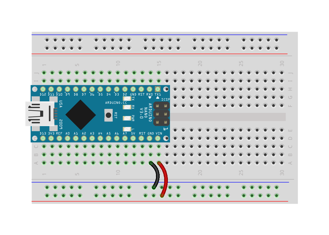
Before beginning, make sure your breadboard is the same way around as the picture below.

The first component in the circuit is the Arduino Nano, which is a simple computer in a convenient package that allows us to connect it to an electronic circuit. The Arduino will be the brain of your RoboSumo robot. You control the robot by writing programs that run on the Arduino.
Make sure your Arduino is the right way around, with the mini USB socket at the end of the breadboard (row 1). Place the breadboard flat on a hard surface before pushing the Arduino into the board. The pin marked D12 should be in breadboard hole H1. Some Arduinos can be very difficult to insert into the breadboard, so if you’re having problems just ask for help because you might have just received a particularly tricky one.
On each side of the breadboard there are two long rows of holes which are connected along the full length of the board. These rails are used to distribute the supply voltage to different parts of the circuit. The blue line marks the negative rail (0V); the red line marks the positive rail (6V in this circuit). The Arduino draws its power from these rails.
The first thing we’ll control with the Arduino is a green light-emitting diode (LED). To do this, we’ll turn the Arduino pin marked D2 into a digital output which means that the program running on the Arduino can set it high (5V) or low (0V). When the pin is set high, a small electrical current flows through the green wire, through the green LED, and finally through the resistor to ground (the negative rail).
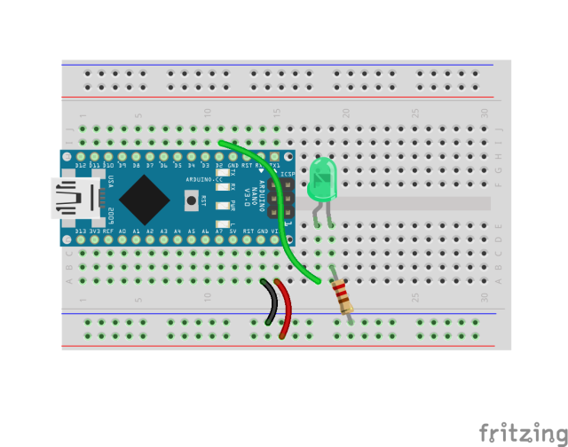
We’re ready to run a program on the Arduino to flash the green LED on and off.
//
// RoboSlam example 1: Blink LED
//

// The setup routine runs once when the power is switched on.
void setup()
{
  // Set pin D2 as a digital output to control the LED
  pinMode(2, OUTPUT);
}

// The loop routine runs over and over until the power is switch off.
void loop()
{
  digitalWrite(2, HIGH); // Turn the LED on
  delay(1000);           // 1000 ms delay
  digitalWrite(2, LOW);  // Turn the LED off
  delay(1000);           // 1000 ms delay
}
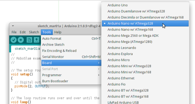
Before running the program on the Arduino Nano, you need to select the exact Arduino board that we are using.
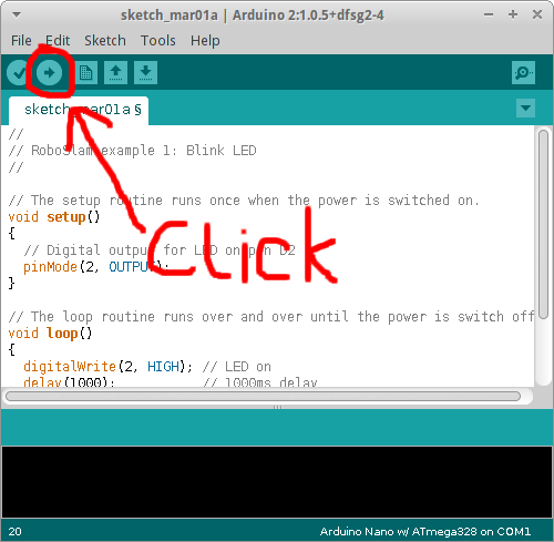
To download and run the program on the Arduino, click the right-facing arrow button on the toolbar of the Arduino IDE:
At this point you should hopefully see the green LED flashing on and off slowly. If it’s not and you can’t figure out why, please ask a facilitator to check what’s wrong.
Once your LED is blinking, there are four things you need to understand before moving on:
Once you understand these four things, you have finished this part of the task (the easy part) and it’s time to move on to the LED Flash Challenge.
In this part, you’re going to modify your circuit to create a simple optical transmitter, which transmits a digital message (a sequence of 1s and 0s) as a series of LED flashes.
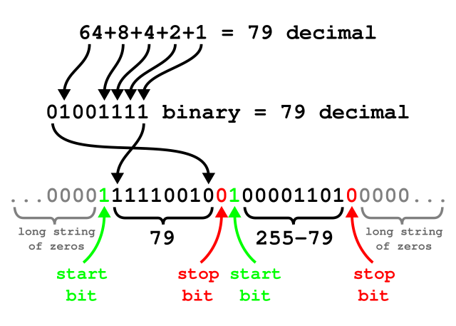
The message that you’ll transmit will be 2 bytes long (a byte is 8 bits; each bit is either one or zero). The first byte will contain your team number. The second byte will contain a number calculated by subtracting your team number from 255 (byte 2).
For example, if your team number is 79...
Allow me to explain how binary numbers work...
Try doing some independent research on binary numbers. There’s lots more great stuff on YouTube, Wikipedia, etc.
Specifically, you need to do the following:
Let’s consider that example team number (79) again. As explained above, byte 1 is 79 and byte 2 is 176.
To summarise, the complete 20-bit sequence for team 79 would be as follows:
The validator for checking your transmission is a web application which I have posted at the following location:
The validator should work on your phone or laptop, but if not then ask your lab instructor. If necessary, they'll set up a validation station in your room where you can record your result once your circuit is working.
If you need help with anything or if something isn't clear, your lab instructor will be happy to help.